Decoding the Language of Circuits Electrical & Electronic Symbols
Ever looked at a circuit diagram and felt like you were deciphering an ancient language? Those squiggles, lines, and circles aren't random doodles; they're a sophisticated system of communication – basic electrical and electronic symbols. Understanding these symbols is fundamental to anyone working with electronics, from hobbyists tinkering with Arduino boards to engineers designing complex systems.
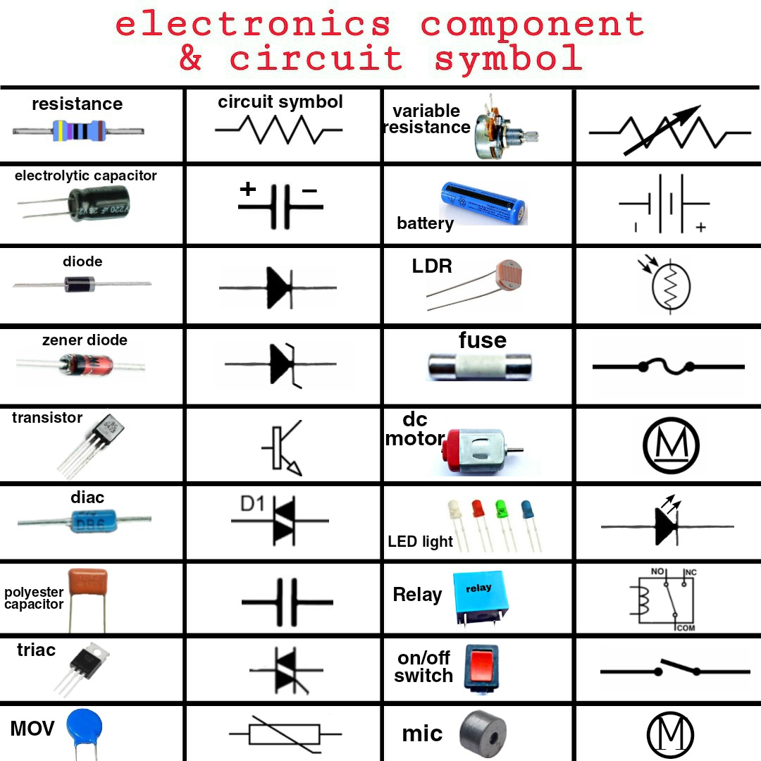
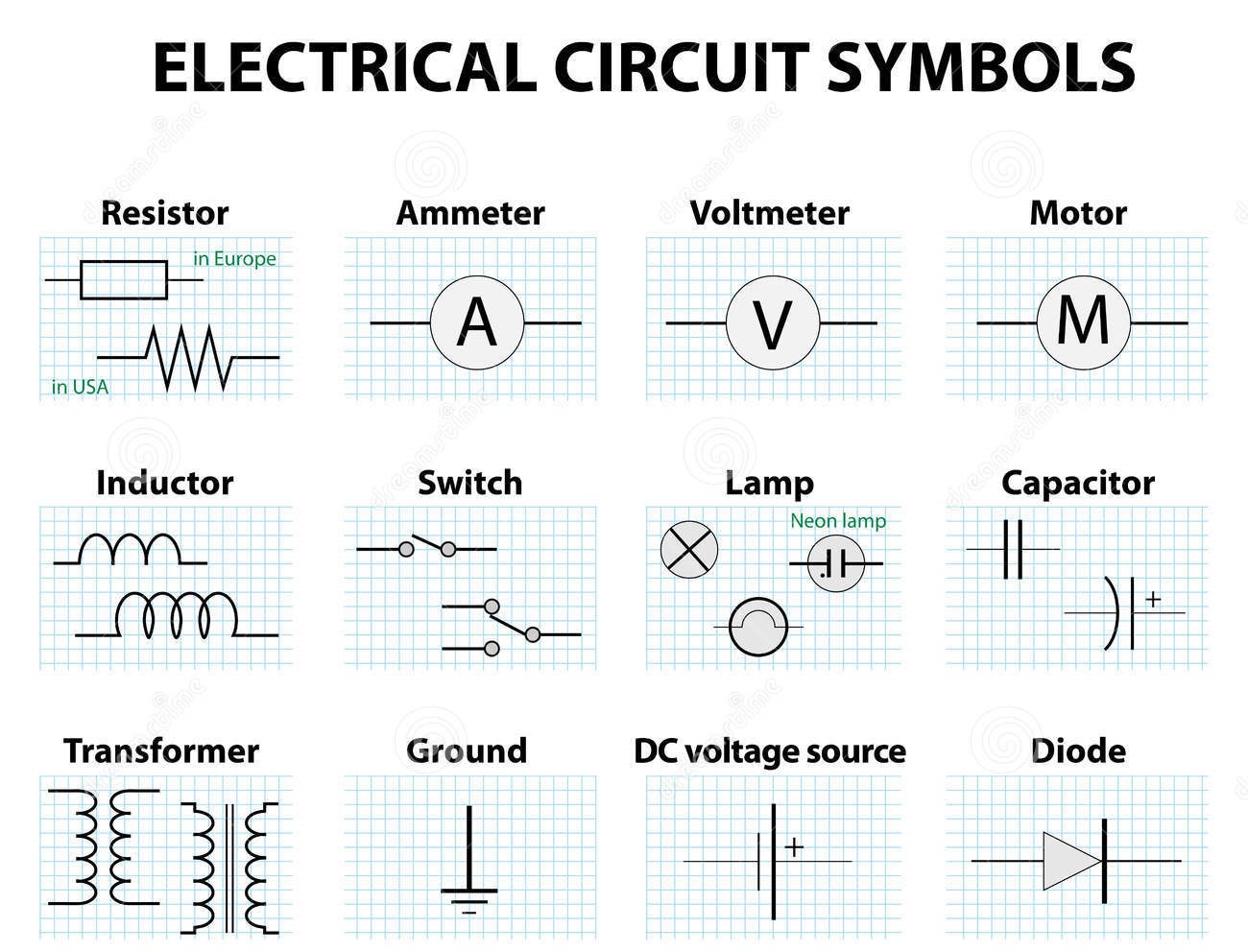
These visual representations are the building blocks of electrical blueprints, enabling us to understand how electricity flows and components interact. Imagine trying to describe a complex circuit using words alone – a daunting task. Electrical and electronics symbols provide a concise and universally understood language, facilitating clear communication among engineers, technicians, and enthusiasts worldwide. These symbols represent various components like resistors, capacitors, transistors, and more, each with its unique form and meaning.
The history of these symbolic representations is intertwined with the development of electricity itself. As electrical experiments evolved, so did the need for a standardized system to depict the various components. Early pioneers like Alessandro Volta and Georg Ohm laid the groundwork for understanding electrical principles, and the symbols gradually emerged as a way to visually represent their discoveries. This evolution has led to the comprehensive system we use today, governed by organizations like the IEEE (Institute of Electrical and Electronics Engineers) to ensure clarity and consistency across different projects and industries.
The importance of correctly interpreting these symbols cannot be overstated. Misinterpreting a single symbol can lead to faulty circuit designs, malfunctioning devices, and even safety hazards. A proper grasp of these symbols allows for efficient troubleshooting, accurate circuit analysis, and the successful construction of electronic devices. For instance, understanding the symbol for a diode, which allows current to flow in only one direction, is crucial for building a rectifier circuit that converts AC to DC power.
Mastering fundamental electrical and electronics diagram symbols is like learning the alphabet of circuitry. Whether you're a seasoned professional or just starting, this knowledge is indispensable for navigating the world of electronics. From simple circuits powering LEDs to complex microchips running our smartphones, these symbols are the key to understanding how it all works. They unlock the secrets of electrical flow, empowering us to design, build, and troubleshoot a wide range of electronic devices.
A resistor, represented by a zigzag line, limits the flow of current. A capacitor, symbolized by two parallel lines, stores electrical energy. Understanding these basic electronic component symbols opens doors to comprehending the function of complex circuits.
Benefits of Using Standardized Electrical and Electronic Symbols:
1. Universal Language: These symbols transcend language barriers, enabling engineers across the globe to collaborate effectively.
2. Simplified Communication: Complex circuit designs can be conveyed concisely and accurately.
3. Efficient Troubleshooting: Identifying faulty components becomes significantly easier with a standardized representation.
Best Practices for Implementing Symbols:
1. Adhere to Standards: Use symbols recognized by organizations like the IEEE.
2. Maintain Consistency: Use the same symbol for the same component throughout a diagram.
3. Clear Labeling: Label components clearly alongside their symbols.
4. Neatness: Ensure the diagram is clean and easy to read.
5. Use Software: Leverage circuit design software for creating professional diagrams.
Advantages and Disadvantages of Standardized Symbols
| Advantages | Disadvantages |
|---|---|
| Clear Communication | Requires Learning |
| International Standard | Potential for Misinterpretation if not used correctly |
Frequently Asked Questions:
1. Where can I find a comprehensive list of electrical symbols? Many resources are available online and in textbooks.
2. Are there different symbols for AC and DC circuits? Yes, some symbols vary to indicate AC or DC operation.
3. How do I learn to read complex circuit diagrams? Start with basic circuits and gradually progress to more complex ones.
4. What software can I use to create circuit diagrams? Several free and paid software options are available, such as Fritzing and Eagle.
5. What is the significance of polarity in electronic symbols? Polarity indicates the direction of current flow or voltage potential.
6. How are integrated circuit (IC) symbols represented? ICs are typically represented by rectangles with pins.
7. Are there resources for learning about obsolete electronic symbols? Yes, some resources archive older symbols.
8. How can I stay updated with the latest symbol standards? Refer to the IEEE and other relevant organizations for updates.
Tips and Tricks:
Familiarize yourself with common symbols first. Use flashcards or online quizzes to memorize them. Practice reading and interpreting simple circuits before tackling complex ones. Join online communities or forums to connect with other enthusiasts and experts.
In conclusion, the world of electronics relies heavily on the clear communication facilitated by standardized electrical and electronic symbols. From simple resistors to complex integrated circuits, these symbols form the language of circuit design. Understanding them is not just about reading diagrams; it's about unlocking the ability to design, build, and troubleshoot electronic devices. By adhering to best practices and continuously learning, we can effectively utilize this symbolic language to push the boundaries of electronic innovation. The benefits of mastering these symbols extend beyond technical proficiency; they open doors to creativity, problem-solving, and a deeper understanding of the technology that shapes our modern world. Embrace this visual language, and you unlock the power to innovate and create within the realm of electronics. As technology advances, so will the complexity of circuits, making the understanding of these fundamental symbols even more critical for future generations of engineers and enthusiasts. Continue exploring, continue learning, and you'll find a world of possibilities waiting to be discovered.
Supercharge your youtube growth with a subscriber countdown widget
Finding names etched in history look up names on the vietnam wall
Black and white fairy tattoo stencil a timeless choice

Basic Electronic Schematic Symbols | Innovate Stamford Now

basic electrical and electronic symbols | Innovate Stamford Now

Electrical Electronic Symbols A Basic Introduction with Chart | Innovate Stamford Now

Table Of Common Electronics Wiring Symbols | Innovate Stamford Now

Basic Important Electrical Symbols and Electronic Symbols | Innovate Stamford Now

Symbols For Electrical Schematics | Innovate Stamford Now

basic electrical and electronic symbols | Innovate Stamford Now

Electronic Schematic Symbols Pdf | Innovate Stamford Now
.jpg)
Circuit Symbols And Diagrams | Innovate Stamford Now

Electronics Wiring Diagram Symbols | Innovate Stamford Now