Decoding the Secrets of Electronic Circuit Diagrams
Ever looked at a complex network of lines, squiggles, and shapes and wondered how it could possibly represent something as powerful as the technology that drives our world? These intricate designs are electronic circuit diagrams, and at their core lies the electronic circuit symbol chart, the key to unlocking the secrets of electronics.
Imagine trying to build a house without blueprints. Similarly, designing electronic circuits without a standardized set of symbols would be chaotic and nearly impossible. The electronic circuit symbol chart provides a universal language for engineers and hobbyists alike, enabling them to communicate and understand complex electronic systems.
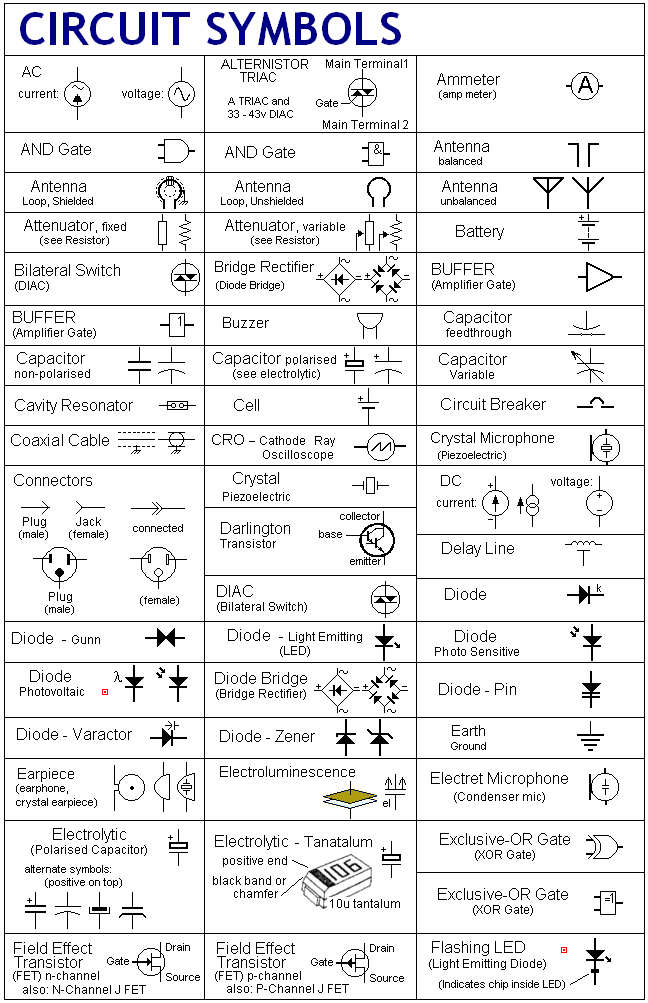
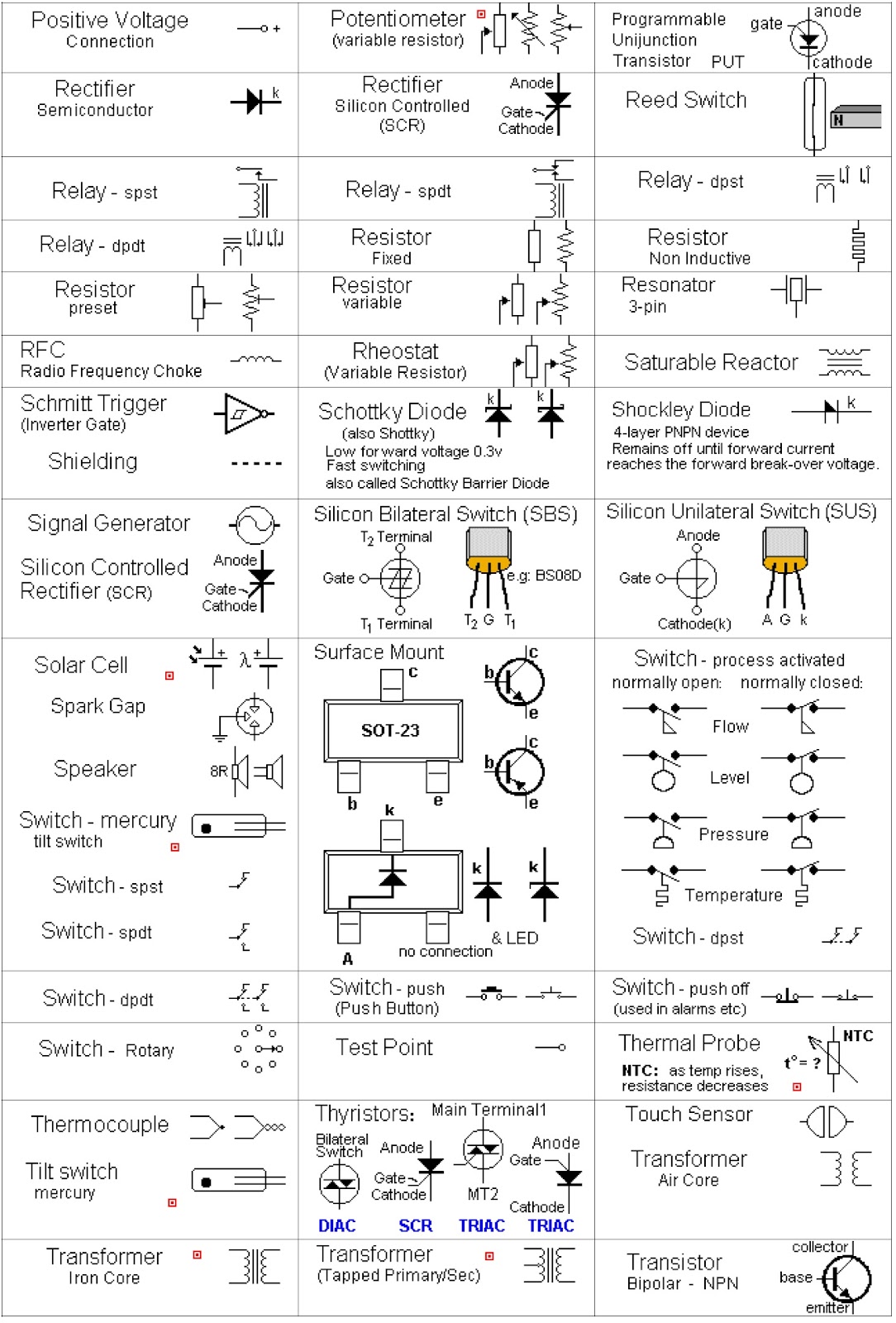
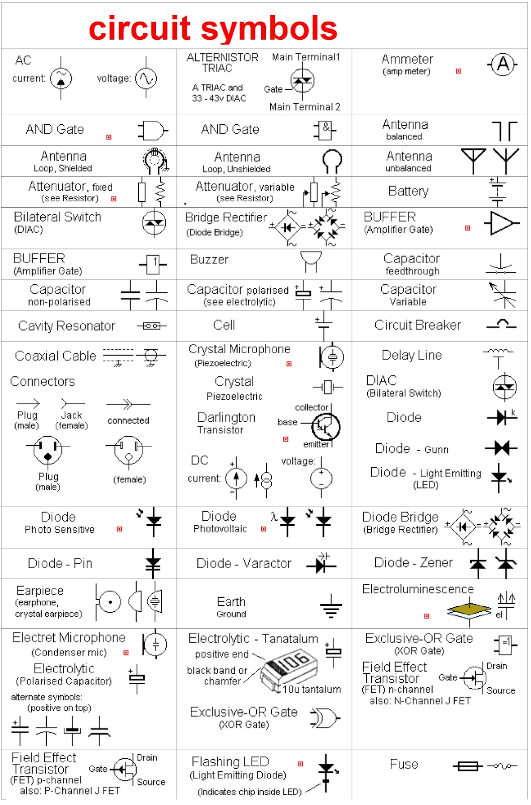
These visual representations of electronic components, from simple resistors to complex microcontrollers, allow for efficient circuit design and troubleshooting. Without a standardized electronic components chart, collaboration would be difficult, and innovation in the field of electronics would be significantly hampered.
The history of electronic circuit symbols is intertwined with the development of electronics itself. As circuits became more complex, the need for a standardized symbolic representation became apparent. Early symbols often resembled the physical components they represented. Over time, these representations evolved into more abstract forms, optimized for clarity and ease of use.
Today, organizations like the IEEE (Institute of Electrical and Electronics Engineers) and IEC (International Electrotechnical Commission) play a crucial role in maintaining and updating these standards, ensuring consistency across the globe. This standardization is vital for international collaboration and the exchange of technical information.
Understanding electronic circuit symbols is fundamental to anyone working with electronics. Whether you're a seasoned engineer or just starting out, a solid grasp of these symbols is essential for designing, building, and troubleshooting circuits. From basic resistor symbols to complex integrated circuit representations, each symbol conveys crucial information about the component's function and characteristics.
One of the primary benefits of using a standardized circuit symbols chart is improved communication. Imagine trying to explain a complex circuit design using only words. The process would be cumbersome and prone to misinterpretations. With a standardized set of symbols, engineers can clearly and concisely convey complex designs, ensuring that everyone is on the same page.
Another significant advantage is enhanced troubleshooting. By visualizing the circuit's components and their connections, technicians can quickly identify faulty components and diagnose issues. This saves valuable time and resources in the repair process.
Furthermore, standardized circuit diagrams facilitate collaboration. Engineers from different backgrounds and regions can seamlessly work together on projects, knowing they share a common understanding of the symbols used in the circuit design.
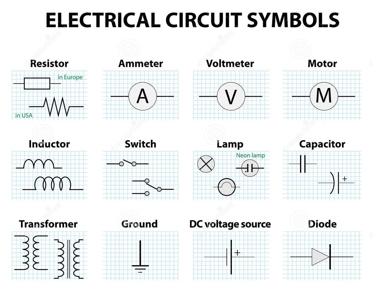
A basic example is the resistor symbol, a zigzag line. This simple symbol immediately tells anyone familiar with electronic circuit diagrams that the component resists the flow of current. Similarly, a capacitor, represented by two parallel lines, indicates a component that stores electrical energy.
Advantages and Disadvantages of Standardized Electronic Circuit Symbols
| Advantages | Disadvantages |
|---|---|
| Improved Communication | Requires Initial Learning |
| Enhanced Troubleshooting | Can Oversimplify Complex Components |
| Facilitates Collaboration | Subject to Standardization Updates |
Best Practice: Always refer to the latest version of the standard electronic components symbols chart.
Best Practice: Ensure consistency in the use of symbols throughout your designs.
Best Practice: Use software tools that incorporate standard electronic circuit symbols.
Best Practice: Clearly label all components and connections in your diagrams.
Best Practice: Regularly review and update your knowledge of electronic circuit symbols.
Real-world example: A simple LED circuit uses symbols for the LED, resistor, and battery/power source.
Real-world example: A complex computer motherboard utilizes numerous symbols for integrated circuits, transistors, capacitors, and more.
Frequently Asked Questions:
Q: Where can I find a comprehensive electronic circuit symbols chart? A: Numerous online resources and textbooks provide detailed charts.
In conclusion, the electronic circuit symbol chart is an indispensable tool in the world of electronics. Its importance stems from its ability to foster clear communication, simplify complex designs, and promote collaboration. From its historical origins to its modern-day applications, the electronic circuit symbols chart remains a cornerstone of electronic engineering. Embrace its power and unlock the potential of electronic circuit design. Begin exploring and learning the language of circuits today, and you'll open doors to a world of technological innovation and creativity.
Gumbo weed company strains
Unlock energy savings with sherwin williams insulative coating
Celebrating quinceaneras in the digital age a guide to online viewing

Schematic Diagrams Circuits Symbols | Innovate Stamford Now

Electrical Electronic Symbols A Basic Introduction With Chart | Innovate Stamford Now

Symbols Used In Circuit Diagrams | Innovate Stamford Now
.jpg)
electronic circuit symbols chart | Innovate Stamford Now

Electrical Symbols in PDF for Free Download | Innovate Stamford Now

What Are The Circuit Symbols | Innovate Stamford Now

Electronic And Electrical Symbols | Innovate Stamford Now

Electrical Symbols in PDF Electric Motor Symbols | Innovate Stamford Now

Electrical Circuit Diagram Symbols List | Innovate Stamford Now

Electrical Diagram Symbols Chart | Innovate Stamford Now

Basic Electronic Schematic Symbols | Innovate Stamford Now