Understanding Motor Symbols in Schematics
Imagine a world without clear communication, a world where instructions are muddled and understanding is a struggle. This is the world of electrical engineering without standardized schematic symbols. These symbols, like the representation for a motor, are the language of circuit design, enabling engineers to convey complex ideas with simplicity and precision.
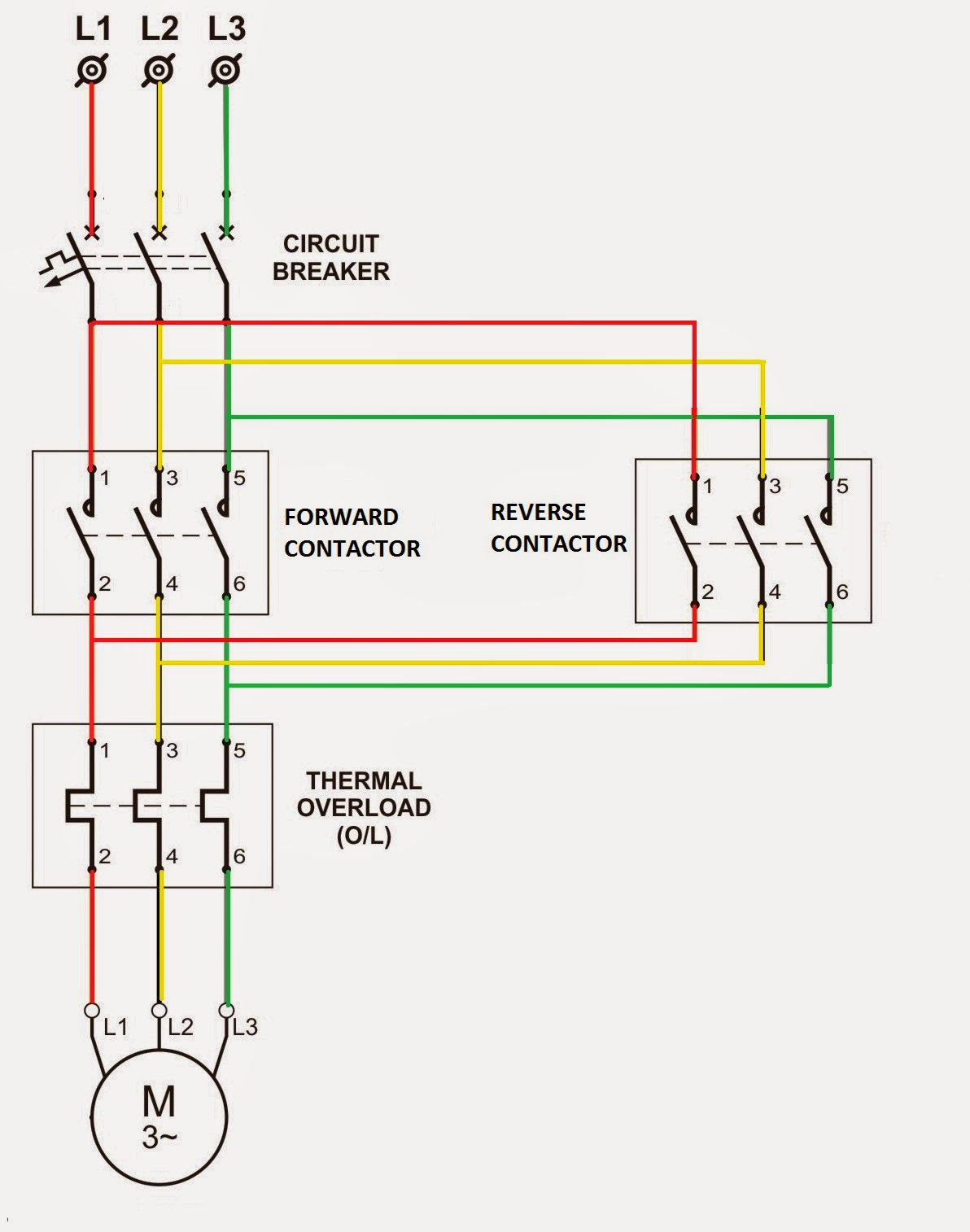
The schematic symbol for a motor, in its various forms, is a fundamental element in electrical diagrams. It provides a visual shorthand for this essential component, allowing engineers to quickly grasp the function and placement of motors within a larger system. Understanding these symbols is crucial for anyone working with electrical circuits, from students to seasoned professionals.
The history of these symbols is intertwined with the development of electrical engineering itself. As electrical systems became more complex, the need for a standardized visual language grew. Early diagrams were often messy and inconsistent, leading to confusion and errors. The evolution towards standardized symbols, including those for motors, was a gradual process driven by the need for clarity and efficiency.
The importance of standardized motor symbols lies in their ability to facilitate communication and prevent misinterpretations. Imagine trying to build a complex machine from a blueprint where the motor is represented differently each time it appears. This would undoubtedly lead to errors and delays. Standardized symbols ensure that everyone involved in a project understands the design intent, promoting smooth collaboration and efficient execution.
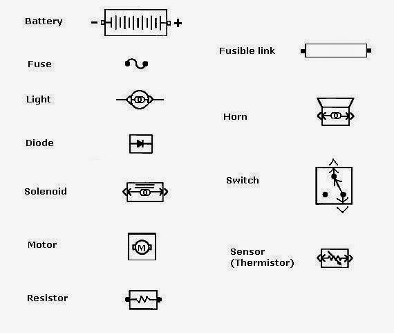
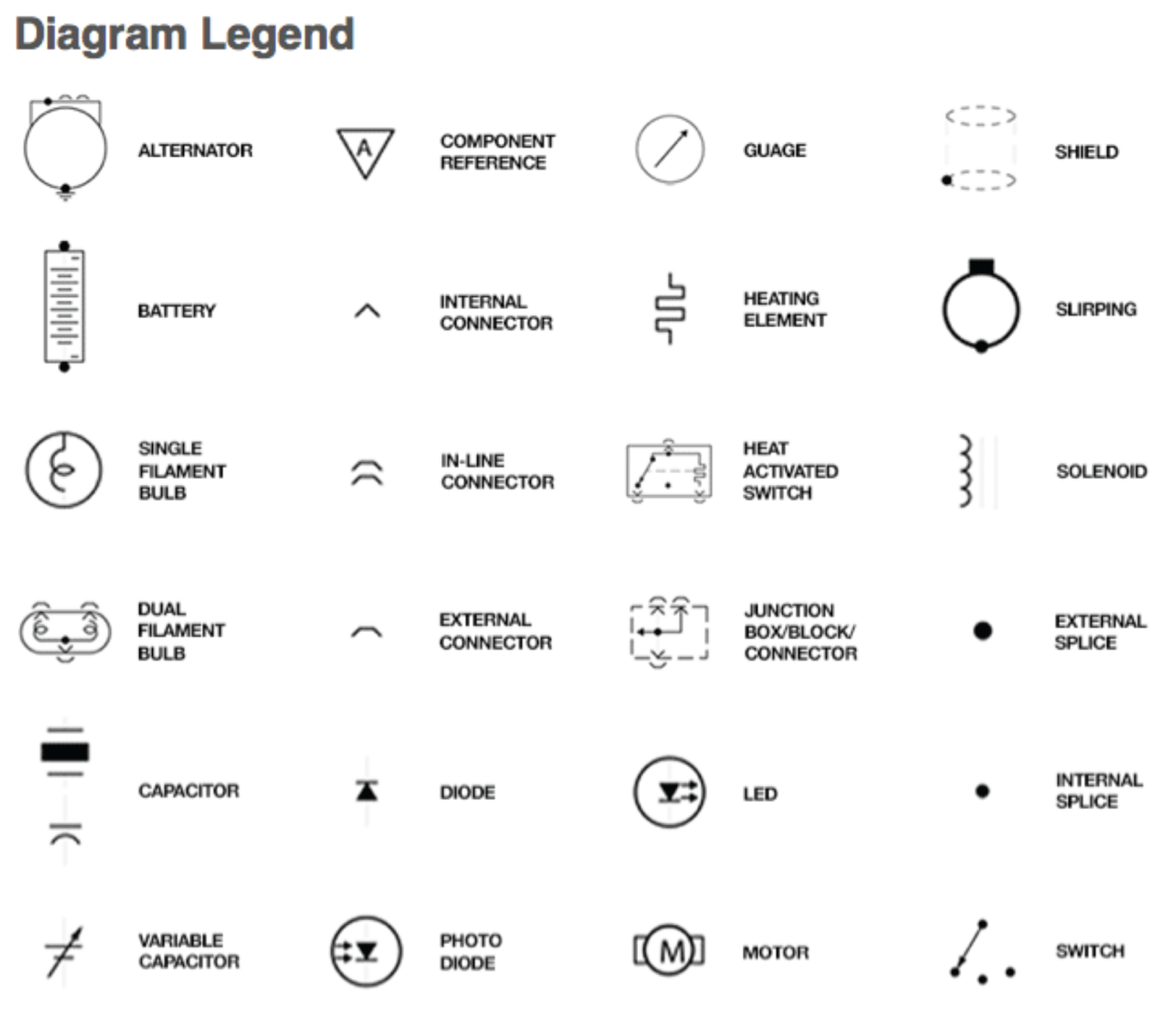
However, even with standardization, there can be subtle variations in motor symbols depending on the specific type of motor or the drawing conventions used. This can sometimes lead to confusion, highlighting the importance of carefully studying the legend or symbol key accompanying a schematic.
A basic motor symbol often consists of a circle with the letter "M" inside. Variations exist to represent different motor types, such as AC motors, DC motors, stepper motors, and servo motors. For instance, a DC motor might be represented by a circle with "M" and a small "D" next to it.
One benefit of using schematic symbols is clarity. They provide a concise way to represent complex components, making diagrams easier to read and understand. For example, instead of drawing a detailed picture of a motor, which would take up valuable space and add unnecessary complexity, a simple symbol conveys the same information efficiently.
Another benefit is universality. Schematic symbols are largely standardized across different industries and countries, facilitating communication between engineers from diverse backgrounds. This shared language eliminates the need for lengthy explanations and reduces the risk of misunderstandings.
Finally, using schematic symbols promotes efficiency in design. By simplifying the representation of components, engineers can focus on the overall system design and functionality rather than getting bogged down in drawing details.
A step-by-step guide to interpreting motor symbols involves first identifying the basic symbol (circle with "M"), then looking for any additional markings that indicate the motor type. Consulting the schematic's legend is crucial for understanding any non-standard symbols.
Advantages and Disadvantages of Standardized Motor Symbols
| Advantages | Disadvantages |
|---|---|
| Clarity and conciseness | Potential for variations and misinterpretations if standards are not adhered to |
| Universality and improved communication | Requires familiarity with standard symbols |
| Enhanced design efficiency | Can oversimplify complex motor characteristics in some cases |
Best practices for using motor symbols include always consulting the schematic's legend, using clear and consistent symbols throughout the diagram, and labeling each motor symbol with a unique identifier.
One common challenge is encountering non-standard symbols. The solution is to always refer to the diagram's legend or consult relevant standards documentation.
Frequently asked questions often revolve around the specific meaning of different motor symbol variations. Resources like engineering handbooks and online forums can provide answers to these questions.
In conclusion, schematic symbols for motors are essential for clear communication in electrical engineering. They provide a concise, universal, and efficient way to represent these crucial components in circuit diagrams. Mastering the use of these symbols is a fundamental skill for anyone working with electrical systems. By understanding the history, variations, and best practices related to these symbols, engineers can ensure clear communication, avoid errors, and streamline the design process. Take the time to study these symbols carefully – it’s an investment that will pay off in clarity and efficiency in all your electrical engineering endeavors.
Unlocking potential the power of letter sized grid paper
Elevate your curb appeal with a sherwin williams green front door
Score a sweet deal salem craigslist cars

Circuit Diagram Of Bldc Motor | Innovate Stamford Now

What Is A Motor Driver Circuit at Jerry Dandridge blog | Innovate Stamford Now

schematic symbol for motor | Innovate Stamford Now

Electrical Wiring Diagram Schematic Symbol Motor Control 49 Images | Innovate Stamford Now

Common Electrical Wiring Symbols | Innovate Stamford Now

Circuit Diagram Motor Symbol | Innovate Stamford Now

schematic symbol for motor | Innovate Stamford Now

Relay Circuit Diagram And Operation | Innovate Stamford Now

schematic symbol for motor | Innovate Stamford Now

View Oil And Gas Plant Electrical Equipment List PNG | Innovate Stamford Now

Timer Relay Schematic Symbol | Innovate Stamford Now

Automotive Electrical Wiring Symbols | Innovate Stamford Now

Circuit Diagram Symbol Motor | Innovate Stamford Now

Motor Control Schematic Symbols | Innovate Stamford Now

Electric Motor Starter Relay | Innovate Stamford Now