Unlocking AC Circuits: Demystifying Phasors in Electrical Engineering
Ever wondered how electrical engineers manage the complexities of alternating current (AC) circuits? The secret lies in a clever mathematical tool called a phasor. Imagine trying to analyze a circuit with constantly fluctuating voltages and currents—it's like trying to hit a moving target. Phasors provide a static representation of these dynamic quantities, making AC circuit analysis much more manageable.
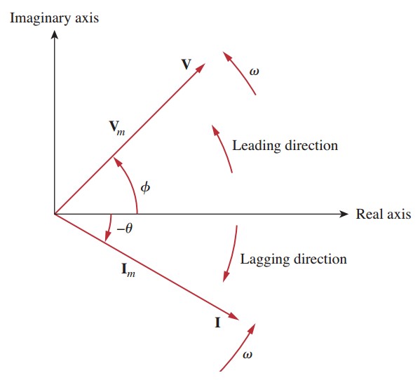
So, what is a phasor in electrical engineering? A phasor is a complex number representing the amplitude and phase of a sinusoidal function, such as the voltage or current in an AC circuit. This representation transforms the time-varying sinusoidal waveforms into stationary vectors, simplifying calculations significantly. Instead of grappling with trigonometric functions, engineers can employ simpler algebraic operations on these phasor quantities.
The concept of phasor analysis originated from the need to simplify complex AC circuit calculations. Early electrical engineers wrestled with cumbersome trigonometric identities when analyzing AC circuits. Charles Proteus Steinmetz, a prominent figure in electrical engineering, is credited with popularizing the use of phasors in the late 19th and early 20th centuries. This innovation revolutionized AC circuit analysis, paving the way for the design and development of sophisticated power systems.
Phasor analysis is fundamental to understanding and designing AC circuits. Its importance lies in its ability to simplify complex calculations involving sinusoidal quantities. Without phasors, analyzing circuits with multiple sources operating at different frequencies would be an incredibly daunting task. Phasors enable engineers to handle these scenarios efficiently and effectively.
One of the main issues associated with phasor analysis is understanding the underlying mathematical concepts. While phasors simplify calculations, they require a grasp of complex numbers and their operations. However, once these principles are mastered, the benefits of phasor analysis far outweigh the initial learning curve.
A phasor is typically represented in polar form as A∠θ, where A is the magnitude (amplitude) of the sinusoidal quantity, and θ is the phase angle relative to a reference. For example, a voltage of 120V with a phase angle of 30 degrees can be represented as 120∠30°. This concise representation encapsulates both the amplitude and phase information of the sinusoidal voltage.
Benefits of using phasors include: 1. Simplified calculations: Phasors allow engineers to use algebraic operations instead of complex trigonometric identities. 2. Clear visualization: Phasor diagrams provide a graphical representation of the relationships between voltages and currents in a circuit. 3. Frequency domain analysis: Phasors facilitate analyzing circuits in the frequency domain, which is crucial for understanding circuit behavior at different frequencies.
Action plan for applying phasors: 1. Identify sinusoidal voltages and currents. 2. Convert these sinusoidal quantities into phasor representations. 3. Perform circuit analysis using phasor algebra. 4. Convert the resulting phasors back to time-domain waveforms if necessary.
Advantages and Disadvantages of Phasor Analysis
| Advantages | Disadvantages |
|---|---|
| Simplifies AC circuit calculations | Requires understanding of complex numbers |
| Facilitates frequency domain analysis | Not applicable to non-sinusoidal waveforms |
Frequently Asked Questions:
1. What is a phasor? A phasor represents a sinusoidal quantity with magnitude and phase.
2. Why are phasors used? They simplify AC circuit analysis.
3. How are phasors represented? They are typically represented in polar or rectangular form.
4. What is the difference between a phasor and a vector? While similar, phasors represent sinusoidal quantities, while vectors can represent any physical quantity.
5. How are phasors used in circuit analysis? They replace sinusoidal functions with complex numbers, allowing for algebraic manipulation.
6. What is the significance of the phase angle in a phasor? It represents the relative time shift of the sinusoidal waveform.
7. What is the relationship between phasors and complex numbers? Phasors are complex numbers used to represent sinusoidal quantities.
8. Can phasors be used for non-sinusoidal waveforms? No, phasors are specifically applicable to sinusoidal functions.Tips and Tricks: Practice converting between time-domain and phasor representations. Familiarize yourself with phasor diagrams and their interpretation. Utilize software tools for complex number calculations.
In conclusion, phasors are indispensable tools in electrical engineering for simplifying the analysis of AC circuits. They transform complex trigonometric calculations into more manageable algebraic operations, enabling engineers to design and analyze sophisticated power systems. Understanding phasors is crucial for anyone working with AC circuits, from power system engineers to electronics designers. Mastering this concept opens the door to a deeper understanding of circuit behavior and empowers engineers to tackle complex electrical challenges with confidence. Embrace the power of phasors and unlock the secrets of AC circuits!
Conquering conversions your guide to metric conversion anchor charts for 4th grade
Unlocking potential fc 24 live editor v24106 deep dive
Unlocking the code your guide to dark anime boy pc setups

Do you know what reactive power compensation is If not keep reading | Innovate Stamford Now

What is Phasor Diagram Definition Theory Steps | Innovate Stamford Now

What is Phasor Diagram Definition Theory Steps | Innovate Stamford Now

Solved How to find peak current in order to express current in a | Innovate Stamford Now

what is a phasor electrical engineering | Innovate Stamford Now

what is a phasor electrical engineering | Innovate Stamford Now

Solved How to find peak current in order to express current in a | Innovate Stamford Now

what is a phasor electrical engineering | Innovate Stamford Now

Ac Source In Circuit Diagram | Innovate Stamford Now

Phasor Diagrams and Phasor Algebra | Innovate Stamford Now

Basic Phasor Diagram Electric Circuit | Innovate Stamford Now

The solution of I can be obtained in the standard form a jb by using | Innovate Stamford Now

what is a phasor electrical engineering | Innovate Stamford Now

what is a phasor electrical engineering | Innovate Stamford Now

How do I transform this sinusoid in phasor | Innovate Stamford Now