Unlocking AC Machine Secrets: The Power of Phasor Diagrams
Ever wondered how engineers tame the complex beast that is an alternating current (AC) machine? The secret lies in a powerful visual tool: the phasor diagram. These diagrams are more than just pretty pictures; they’re the Rosetta Stone for understanding the intricate dance of voltages, currents, and magnetic fields within motors, generators, and transformers. They unlock a deeper understanding of AC circuit behavior and empower engineers to optimize machine performance like never before.
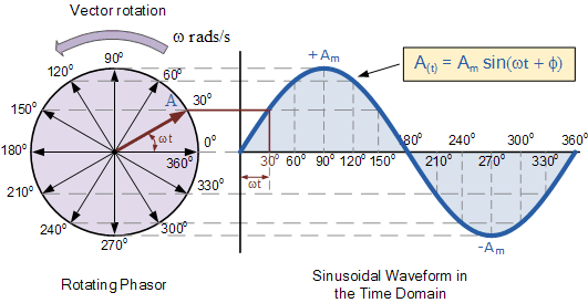
Phasor diagrams provide a simplified representation of sinusoidal quantities in AC circuits, essentially freezing the rotating vectors in time to analyze their relationships. Instead of grappling with complex trigonometric functions, engineers can visualize these quantities as static vectors, making analysis much more intuitive. This graphical approach makes complex calculations easier to grasp, enabling quick insights into system behavior and facilitating efficient problem-solving.
The concept of phasor representation emerged from the need to simplify AC circuit analysis. Early electrical engineers wrestled with complicated mathematical expressions, but Charles Proteus Steinmetz, a pioneer in electrical engineering, introduced the idea of using complex numbers and graphical representations to simplify calculations. This innovation revolutionized the field, making AC circuit analysis significantly more accessible and paving the way for the widespread adoption of AC power systems.
Phasor diagrams are essential for understanding the fundamental principles governing AC machine operation. They reveal the relationships between voltage, current, and impedance, illustrating how these quantities interact to influence power flow and efficiency. Without phasor diagrams, analyzing and designing AC machines would be significantly more challenging, hindering advancements in power systems and electrical technology.
A major challenge in using phasor diagrams is understanding the concept of phase difference. Since AC quantities are constantly changing, their relationships are defined not only by magnitude but also by their relative phase shift. Accurately representing and interpreting these phase relationships is crucial for correctly analyzing AC circuit behavior and avoiding misinterpretations that can lead to design flaws or operational issues.
Simply put, a phasor diagram represents a sinusoidal quantity as a rotating vector. The length of the vector corresponds to the magnitude of the quantity, while its angle represents the phase shift relative to a reference phasor. For example, in a simple RLC circuit, the voltage across the resistor is in phase with the current, while the voltage across the inductor leads the current by 90 degrees, and the voltage across the capacitor lags the current by 90 degrees. These phase relationships are clearly depicted in the phasor diagram, simplifying the analysis of circuit behavior.
Benefits of using phasor diagrams include: 1) Simplified analysis: They transform complex trigonometric equations into visual representations, making analysis easier and more intuitive. 2) Improved understanding: They provide a clear picture of phase relationships between voltage and current, crucial for understanding AC circuit behavior. 3) Efficient problem-solving: They allow engineers to quickly identify and address issues related to power factor, voltage regulation, and other critical aspects of AC machine operation.
Advantages and Disadvantages of Phasor Diagrams
| Advantages | Disadvantages |
|---|---|
| Simplifies complex AC circuit analysis | Can be challenging to understand initially, especially phase relationships |
| Provides a visual representation of voltage, current, and impedance relationships | Limited to steady-state analysis and doesn't capture transient behavior |
| Facilitates understanding of power factor and other key concepts | Can become complex for highly intricate circuits |
Best Practices: 1. Always choose a reference phasor. 2. Accurately represent magnitudes and phase angles. 3. Clearly label all phasors. 4. Use appropriate scaling for clarity. 5. Consider using software tools for complex diagrams.
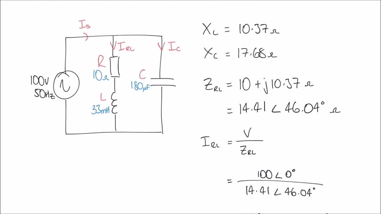
Examples: Phasor diagrams are used in analyzing synchronous motors, induction motors, transformers, and power systems. They are essential for designing and optimizing these machines for efficient and reliable operation.
Challenges can include difficulty visualizing 3-phase systems or interpreting complex diagrams. Solutions include using software tools or breaking down the diagram into simpler components.
FAQ: What is a phasor? What is phase difference? How are phasor diagrams used in motor analysis? What are the limitations of phasor diagrams? How can I learn more about phasor diagrams? What software can I use to create phasor diagrams? Why are phasor diagrams important for power system analysis? How are phasor diagrams used in transformer analysis?
Tips & Tricks: Utilize software tools to generate accurate and complex diagrams. Start with simple circuits before tackling complex systems. Practice interpreting existing diagrams to build your understanding.
In conclusion, phasor diagrams are an indispensable tool for any engineer working with AC machines. They provide a powerful visual language for understanding complex circuit behavior, simplifying analysis, and facilitating the design and optimization of electrical systems. Mastering the art of phasor diagrams is essential for unlocking the full potential of AC machines and pushing the boundaries of electrical innovation. From optimizing motor efficiency to designing robust power systems, the ability to effectively utilize phasor diagrams is a critical skill for any aspiring electrical engineer. So, dive into the world of phasor diagrams and empower yourself with the knowledge to conquer the complexities of AC circuits.
Unlocking the nutritional power of wheat bran cereal
Herren jacken bei amazon your guide to navigating the jacket jungle
Alcohol in the workplace navigating the complexities

Rl Circuit Phasor Diagram | Innovate Stamford Now

phasor diagrams of ac machines | Innovate Stamford Now

Equivalent Circuit And Phasor Diagram Of Synchronous Machine | Innovate Stamford Now

Phasor Diagram 3 Phase Ac Circuit | Innovate Stamford Now

Ac Rlc Circuits Phasor Diagrams | Innovate Stamford Now
Schneider Electric Phasor Diagram | Innovate Stamford Now

Induction Motor Phasor Diagram | Innovate Stamford Now

Phasor diagram of synchronous machines 28 | Innovate Stamford Now

What is a phasor diagram | Innovate Stamford Now
Rlc Phasor Diagram Generator | Innovate Stamford Now

Phasor Representation Of One Phase AC Circuit Presentation | Innovate Stamford Now

Phasor Diagram 3 Phase Ac Circuit | Innovate Stamford Now

Synchronous Motor Equivalent Circuit Phasor Diagram | Innovate Stamford Now

Phase Diagram Of Rl Circuit | Innovate Stamford Now

Series Rlc Circuit Phasor Diagram | Innovate Stamford Now