Unlocking the Secrets of Motor Control Circuit Diagrams
Ever feel like you're navigating a labyrinth of wires and components when dealing with motors? Understanding the intricate dance between electricity and motion can feel mystifying. But what if you had a roadmap, a visual guide to decipher the language of motor control? That's where the power of a motor control schematic diagram comes in. It's the secret key to unlocking a deeper understanding of how these systems work, empowering you to troubleshoot, design, and even optimize motor control with confidence.
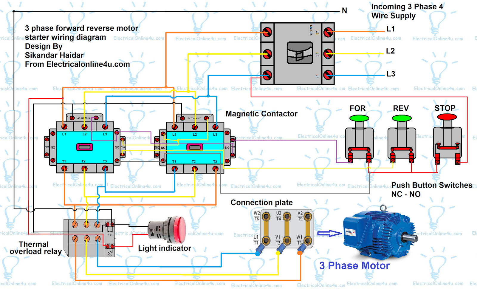
Motor control circuit diagrams, also known as wiring diagrams or schematics, are essential tools for anyone working with electric motors. They provide a visual representation of the electrical connections and components that make up a motor control system. Think of them as the blueprints of your electrical setup, revealing the flow of energy and the logic behind the motor's movements. Imagine trying to assemble a complex piece of furniture without instructions – it's almost impossible. Similarly, navigating the complexities of motor control without a schematic diagram can be incredibly challenging.
The history of motor control schematic diagrams is intertwined with the development of electric motors themselves. As motors became more sophisticated, so did the need for clear and concise representations of their control circuits. Early diagrams were often hand-drawn, but with advancements in technology, computer-aided design (CAD) software has become the standard for creating detailed and accurate schematics. These diagrams are crucial for ensuring the safety and efficiency of motor control systems, preventing costly errors and downtime.
One of the biggest issues surrounding motor control schematics is misinterpretation or lack of understanding. A seemingly small error in a diagram can lead to significant problems, from improper motor operation to potential safety hazards. This underscores the importance of proper training and education in interpreting and using these diagrams effectively. Imagine using a recipe with incorrect measurements – the outcome could be disastrous. The same principle applies to motor control; accurate interpretation of the schematic diagram is essential for achieving the desired results.
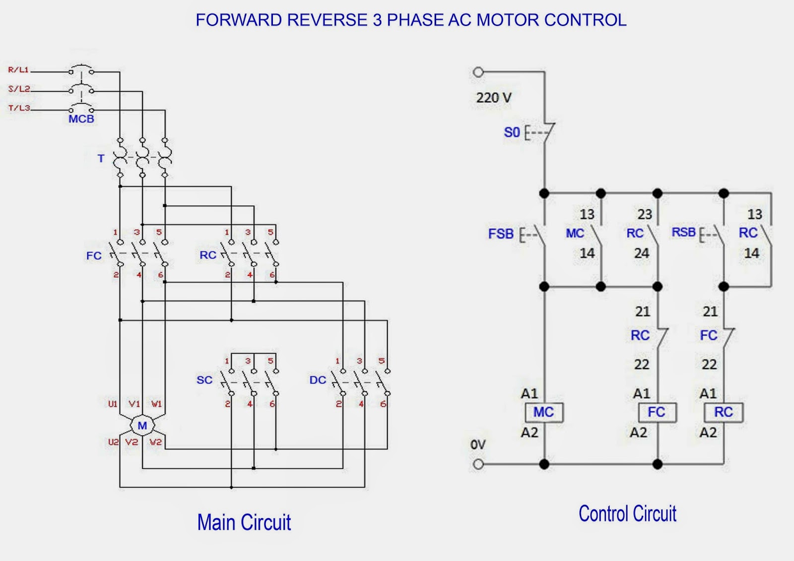
Understanding the various symbols and conventions used in motor control schematic diagrams is paramount. These symbols represent different components, such as switches, relays, contactors, and overload protection devices. Being able to decipher these symbols is like learning a new language, allowing you to fluently read and understand the "story" being told by the diagram. For instance, a normally open contact is represented by two parallel lines, while a normally closed contact is represented by two parallel lines with a diagonal line across them. Mastering these symbols is fundamental to interpreting the overall circuit design.
Advantages and Disadvantages of Using Motor Control Schematic Diagrams
| Advantages | Disadvantages |
|---|---|
| Troubleshooting | Requires Specialized Knowledge |
| Design and Implementation | Can be Complex for Large Systems |
| System Optimization | Potential for Errors if Misinterpreted |
Best Practices for Implementing Motor Control Schematics:
1. Use Standard Symbols: Adhere to industry-standard symbols for clarity and consistency.
2. Clear Labeling: Label all components and connections clearly to avoid confusion.
3. Version Control: Maintain different versions of the schematic as the design evolves.
4. Review and Verification: Always have another engineer review the schematic before implementation.
5. Proper Documentation: Document any changes or modifications made to the original schematic.
Frequently Asked Questions:
1. What is a motor control schematic diagram? (Answer: A visual representation of the electrical connections of a motor control system.)
2. Why are these diagrams important? (Answer: They are essential for troubleshooting, design, and optimization.)
3. What are some common symbols used? (Answer: Examples include symbols for switches, relays, and contactors.)
4. How can I learn to read these diagrams? (Answer: Through training, education, and practice.)
5. What are the benefits of using CAD software? (Answer: Creates accurate and detailed schematics.)
6. What are some common mistakes to avoid? (Answer: Misinterpretation of symbols and incorrect wiring.)
7. How can I improve my understanding of motor control schematics? (Answer: Study resources and practice interpreting diagrams.)
8. Where can I find examples of motor control schematics? (Answer: Textbooks, online resources, and manufacturer documentation.)
In conclusion, understanding and utilizing motor control schematic diagrams is crucial for anyone working with electric motors. These diagrams are the foundation upon which efficient, safe, and reliable motor control systems are built. They provide a roadmap for navigating the complexities of electrical connections, empowering engineers and technicians to troubleshoot problems, design new systems, and optimize existing ones. Mastering the language of these diagrams is an investment in your skills and knowledge, unlocking the potential to create sophisticated and effective motor control solutions. By embracing the power of the schematic, you can transform from a novice to a confident master of the electrical domain, harnessing the power of motors to drive innovation and efficiency in countless applications.
Level up your content the ultimate guide to choosing a killer gaming channel name
Unlocking fun your guide to the teka silang kata generator
Modern quinceanera cakes torta de 15 anos modernas

555 DC Motor Speed Control pcb | Innovate Stamford Now

Motors And Motor Control Circuits | Innovate Stamford Now

Single Line Diagram For Motor | Innovate Stamford Now

Electrical Schematic Symbols Motor Control | Innovate Stamford Now

The Essential Guide to Start | Innovate Stamford Now

Basic Electrical Schematic Diagrams | Innovate Stamford Now

Improve Simple Pwm Circuit Diagram | Innovate Stamford Now

Motor Control Schematic Symbols | Innovate Stamford Now

DIAGRAM Complex Motor Control Wiring Diagrams | Innovate Stamford Now

DIAGRAM Three Phase Motor Control Circuit Diagram | Innovate Stamford Now

Electric Motor Starter Relay | Innovate Stamford Now
Forward Reverse Motor Control Diagram For 3 Phase Motor | Innovate Stamford Now

Control Circuit Schematic Diagram | Innovate Stamford Now
Schematic Diagram Motor Control | Innovate Stamford Now
Single Phase Motor Circuit Diagram | Innovate Stamford Now