Unraveling the Ignition Coil Wiring Diagram
The subdued hum of a well-tuned engine is a symphony of precisely timed explosions, orchestrated by a critical component: the ignition coil. But behind this seemingly simple act of combustion lies a complex electrical ballet, guided by the ignition coil wiring diagram. Understanding this blueprint is essential for any automotive enthusiast, mechanic, or DIYer seeking to master the heart of their vehicle.
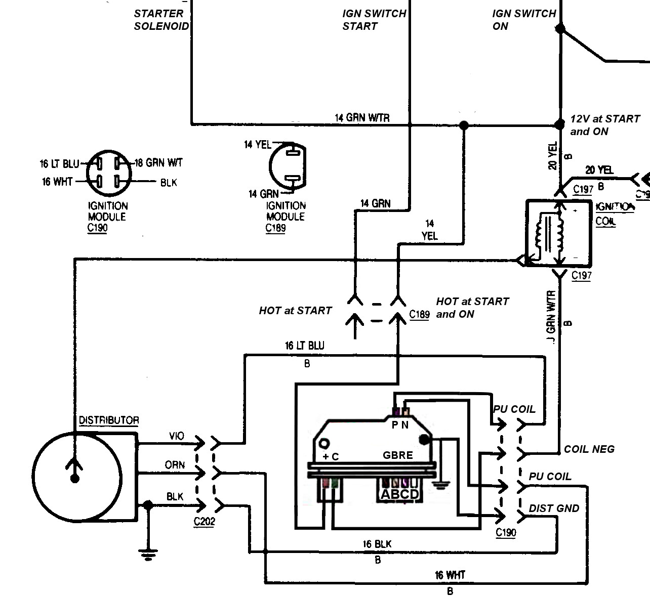
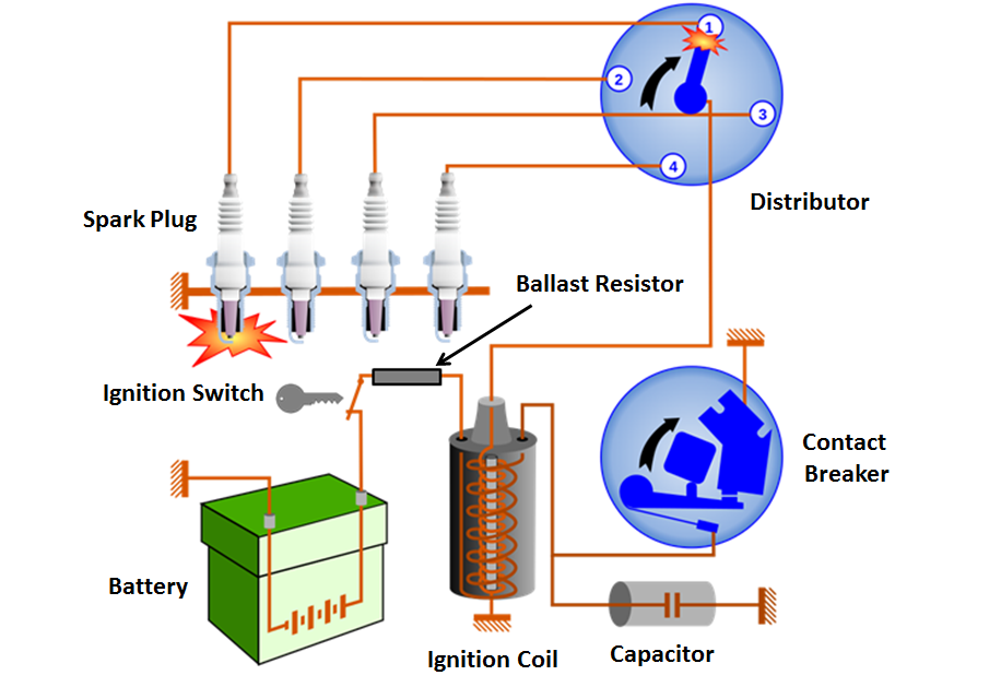
An ignition coil, at its core, is a transformer that elevates the low voltage from the battery to the high voltage required to generate a spark across the spark plug gap. This spark ignites the air-fuel mixture, driving the pistons and ultimately powering the vehicle. The ignition coil circuit diagram maps out this electrical pathway, detailing the flow of current from the battery, through the primary and secondary windings of the coil, and ultimately to the spark plug. Deciphering this diagram is key to diagnosing and resolving ignition issues.
The evolution of the ignition coil wiring diagram mirrors the advancements in automotive technology. From early contact breaker points systems to modern electronic ignition modules, the underlying principle remains the same: to amplify voltage and deliver a precisely timed spark. However, the complexity of the wiring has evolved, reflecting the increasing sophistication of engine management systems. Understanding this evolution helps in appreciating the nuances of different ignition system designs and their respective wiring diagrams.
The ignition coil wiring schematic is indispensable for troubleshooting a variety of engine problems. A faulty coil, a broken wire, or a corroded connection can all manifest as misfires, rough idling, or a complete failure to start. By consulting the ignition coil diagram, one can systematically trace the electrical pathway, identify the source of the problem, and implement the necessary repairs. This knowledge empowers you to take control of your vehicle's maintenance and avoid costly repairs.
Beyond troubleshooting, a thorough understanding of the ignition coil electrical diagram is crucial for performance tuning. Modifying the ignition system, such as upgrading to a higher-output coil, requires careful consideration of the wiring and its impact on the overall system. A well-interpreted diagram provides the roadmap for safely and effectively enhancing engine performance.
An ignition coil diagram typically depicts the primary and secondary windings, the connections to the battery and the ignition module (or contact breaker points in older systems), and the pathway to the distributor (if applicable) and ultimately the spark plugs. The diagram also indicates the polarity of the connections, crucial for proper operation.
Benefits of understanding ignition coil diagrams include efficient troubleshooting, informed maintenance, and the ability to perform performance upgrades.
A simple action plan for using an ignition coil diagram involves identifying the specific system in your vehicle, locating the corresponding diagram, and tracing the electrical pathway to diagnose potential issues or plan modifications.
Advantages and Disadvantages of Understanding Ignition Coil Diagrams
| Advantages | Disadvantages |
|---|---|
| Empowered troubleshooting | Requires some electrical knowledge |
| Informed maintenance | Diagrams can be complex for some systems |
| Facilitates performance upgrades | Misinterpretation can lead to incorrect repairs |
Best practices for using ignition coil diagrams include using the correct diagram for your specific vehicle model and year, understanding the symbols and conventions used in the diagram, and exercising caution when working with high-voltage components.
Frequently Asked Questions: What is the primary winding? What is the secondary winding? How does the coil generate high voltage? What are common symptoms of a faulty coil? How do I test an ignition coil? Where can I find the ignition coil diagram for my car? What safety precautions should I take when working with the ignition system? How do different ignition system types (e.g., distributorless ignition system) affect the diagram?
In conclusion, the ignition coil wiring diagram is far more than just lines and symbols; it’s the key to unlocking the power and performance of your engine. From diagnosing a simple misfire to embarking on ambitious performance upgrades, this diagram provides the essential knowledge for mastering your vehicle’s ignition system. By understanding its intricacies, you empower yourself to maintain, troubleshoot, and even enhance your engine’s performance. Take the time to study the diagram, familiarize yourself with its components, and unlock the potential that lies within your vehicle's ignition system. This knowledge will not only save you time and money but also give you the confidence to tackle any ignition-related challenge.
Level up your visuals delving into the world of dd character art generators
Unleash your inner artist the simple joy of an easy skull drawing
Finding your cars neutral safety switch a comprehensive guide

12v Ignition Coil Ballast Resistor Wiring Diagram | Innovate Stamford Now

Ignition Coil Circuit Diagram | Innovate Stamford Now

Ignition Coil Schematic Diagram | Innovate Stamford Now

Ignition Switch Schematic Diagram | Innovate Stamford Now

How To Wire An Ignition Coil Diagram | Innovate Stamford Now

1986 Gm Ignition Switch Wiring Diagram | Innovate Stamford Now

How Hot Does A Ignition Coil Get at Curtis English blog | Innovate Stamford Now

How To Wire A Coil Pack | Innovate Stamford Now

Ignition Coil Wiring Diagram Manual | Innovate Stamford Now

Coil On Plug Ignition Diagram Car | Innovate Stamford Now

1966 Ford Mustang Ignition Switch | Innovate Stamford Now

Gm Ignition Module Wiring Schematic | Innovate Stamford Now

Ignition Coil B Primary Secondary Circuit | Innovate Stamford Now

Ignition Coil Schematic Diagram | Innovate Stamford Now

Schematic Of Ignition Coil | Innovate Stamford Now