Unveiling the Secrets of the Induction Motor: A Journey into the Circle Diagram
Within the intricate realm of electrical machinery, the three-phase induction motor stands as a workhorse of modern industry, silently powering countless applications. But how do we truly grasp the inner workings of this ubiquitous machine? One particularly insightful tool, the circle diagram, offers a graphical window into the motor's performance characteristics, unlocking a deeper understanding of its behavior under varying loads.
The circle diagram, a graphical representation of the induction motor's performance, provides a visual tapestry of power, torque, and efficiency. This elegant representation transforms complex mathematical relationships into a readily interpretable form, allowing engineers to predict and analyze motor behavior with relative ease.
Historically, the circle diagram emerged as a powerful tool for analyzing induction motor performance before the advent of sophisticated computer simulations. Its origins lie in the application of geometrical principles to the equivalent circuit of the motor, transforming a network of resistances and reactances into a visually intuitive circle. This graphical approach revolutionized motor analysis, providing engineers with a practical method for predicting and optimizing performance.
The significance of the circle diagram lies in its ability to predict crucial motor parameters such as output power, torque, efficiency, and power factor under different load conditions. This information is essential for selecting the right motor for a specific application and for ensuring its efficient operation.
However, the circle diagram is not without its limitations. It relies on certain simplifying assumptions, such as neglecting magnetic saturation and core losses, which can affect the accuracy of the results, particularly at higher loads. Despite these limitations, the circle diagram remains a valuable tool for understanding the fundamental principles of induction motor operation.
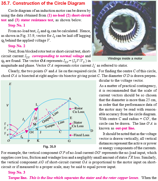
The construction of a circle diagram involves plotting various motor parameters, such as input power, current, and slip, on a complex plane. The resulting locus of points forms a circle, hence the name. Different points on the circle correspond to different operating conditions of the motor, allowing for a comprehensive analysis of its performance across a range of loads.
One of the key benefits of the circle diagram is its ability to predict the maximum torque that the motor can develop. This information is critical for applications requiring high starting torque or for ensuring that the motor does not stall under heavy loads. Another benefit is the ability to determine the motor's operating efficiency at different load points, enabling engineers to optimize performance and minimize energy consumption.
Furthermore, the circle diagram provides insights into the motor's power factor, which is a measure of how effectively the motor utilizes the supplied power. A high power factor is desirable for minimizing power losses and improving overall system efficiency. The circle diagram allows engineers to analyze the impact of load on the power factor and to implement corrective measures if necessary.
Advantages and Disadvantages of Circle Diagram
| Advantages | Disadvantages |
|---|---|
| Visual representation simplifies complex relationships | Based on simplifying assumptions, neglecting some factors |
| Predicts key performance parameters like torque and efficiency | Accuracy can decrease at higher loads due to neglected factors |
| Facilitates motor selection and optimization | Can be complex to construct for some motor types |
Frequently Asked Questions about Circle Diagram of Three Phase Induction Motor:
1. What is a circle diagram? A graphical representation of the performance characteristics of a three-phase induction motor.
2. What information does it provide? Data on torque, efficiency, power factor, and other key parameters.
3. Why is it important? Helps in understanding and predicting motor behavior under different loads.
4. What are its limitations? Relies on simplifying assumptions, which can affect accuracy.
5. How is it constructed? By plotting various motor parameters on a complex plane.
6. How does it help in motor selection? Allows comparison of different motors based on their performance curves.
7. Can it be used for all types of induction motors? While generally applicable, its accuracy varies for different motor designs.
8. What are alternatives to circle diagram analysis? Computer simulations and direct measurement techniques.
In conclusion, the circle diagram stands as a testament to the power of visualization in understanding complex systems. While modern computer simulations offer greater accuracy and detail, the circle diagram continues to provide a valuable pedagogical tool for grasping the fundamental principles of induction motor operation. Its ability to visualize the interplay of power, torque, and efficiency provides engineers with a powerful tool for optimizing motor performance and ensuring reliable operation in countless applications. By understanding the nuances of the circle diagram, we gain a deeper appreciation for the elegant simplicity with which we can unravel the complexities of the electrical world.
Inked faith exploring the trend of forearm tattoos for men with bible verses
Unlocking the power of the green circular arrow
Elevate your home with benjamin moore bear creek

Schematic Diagram Of 3 Phase Induction Motor | Innovate Stamford Now

Basic Wiring Diagram For 3 Phase Motor | Innovate Stamford Now

Three Phase Induction Motor Circuit Diagram | Innovate Stamford Now

Types of Single Phase Induction Motors | Innovate Stamford Now

Equivalent Circuit Diagram Of Induction Motor | Innovate Stamford Now

Introduction on Induction Machines | Innovate Stamford Now

Ac Induction Motor Working Principle | Innovate Stamford Now

Induction motor with squirrel | Innovate Stamford Now

circle diagram of three phase induction motor | Innovate Stamford Now

DIAGRAM Cross Section Of An Induction Motor Diagram | Innovate Stamford Now

3 Phase Induction Motor Definition And Working Principle | Innovate Stamford Now

Three Phase Motor Diagram | Innovate Stamford Now

How To Wire A Star Delta Motor | Innovate Stamford Now

15 Circle Diagram Of Induction Motor | Innovate Stamford Now

Induction Motor Wiring Diagrams | Innovate Stamford Now